When systems crystallize, they adopt the structure whose configuration has the lowest energy crystal structure. In ionic solids, this is mainly determined by the coulombic interaction between the ions: a maximization of the attractive forces between oppositely charged ions and a minimization of the repulsion between like charged ions.
The arrangement of ions in a crystal is known as the crystal structure.
Crystal Structure
The crystal structure is made up of a periodically repeating structural motif known as the unit cell. This is the basic component of the structure, which, when repeated in three dimensions by translational moves only, makes up the complete structure. There may be a choice of unit cells for a given system, such that when repeated give the same overall crystal structure. The one usually adopted as the standard is the one which has the same symmetry as the crystal as a whole.
The pattern of ions or atoms within the structure is given by the lattice. A lattice point need not be a particular ion, but may be a set of ions or atoms, which can be repeated to give the structure. The group of ions associated with a given lattice point are known as the basis for the cell.
Thus if the lattice and the unit cell is known, the entire structure may be elucidated.
In discussing the structures of metals and ionic solids, we generally consider the ions to be spherical objects, or a size given by the ionic radius of the ion, and some of the simplest structures can be understood in terms of the best possible packing arrangements of these spheres. These structures are the ones in which the occupied volume is minimized, and lead to the idea of close-packing of spheres.
Close Packed Structures
Close Packed structures have the highest occupied volume and each sphere has the maximum number of neighbours, or the highest coordination number. In many metals, for example, the close packing of spheres leads to there being twelve nearest neighbours, and hence a coordination number of 12.
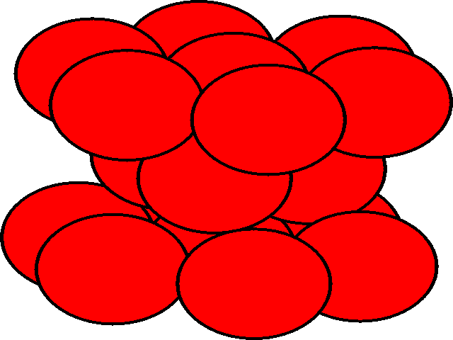
When a layer of close packed spheres is formed, another layer may be placed on top, with each of the spheres in the second layer falling into the basin made by three of the spheres in the second row. However, when a third layer is placed on top of the second layer, there are two different orientations of this third layer with respect to the first layer. If the third layer spheres are in position 1, then they are directly above the spheres in the first layer, and this gives a layer structure known as ABA (ie. the third layer is the same as the first, but the second is different to both). If the third layer is in position 2, then the spheres of the third layer are over the holes in the first layer, and this gives a layer structure known as ABC (ie. all three layers are in different relative orientations).
| Close packing of spheres | ||
| Close packing of two layers of spheres. The two possible positions for the spheres of the third layer are labeled 1 and 2 | Third layer spheres occupy positions 1. This gives ABA packing. | Third layer spheres occupy positions 2. This gives ABC packing. |
 |
 |
 |
The ABA packing is also known as hexagonal close packing, and the ABC packing is also known as cubic close packing.
| Close packing of spheres: 3D structures | |
| hexagonal close packing (hcp) | cubic close packing (ccp) |
 |
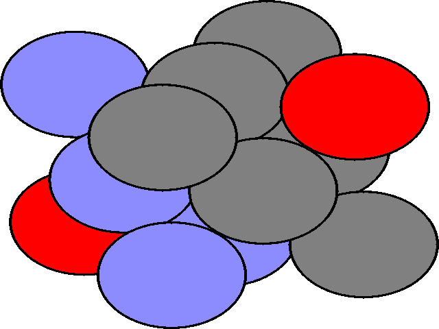 |
| The ABA arrangement of spheres is shown in three dimensions. | The ABC arrangement of atoms is shown, rotated relative to the hcp view. The different colours show the A, B, and C layers. |
 |
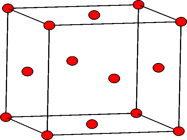 |
| The hcp structure shown in lattice form. The atoms in the second layer are at the center of three of the triangular prisms. | The ccp structure shown in lattice form. There are atoms at the 8 corners of the cube, and also in the centers of the 6 faces of the cube. |
If one considers the lattice form of the ccp structure shown, we can see that the unit cell contains 8 atoms at the corners, and 6 atoms in the faces, specifically one in the center of each face. This structure is also known as the face centered cubic structure (fcc). It should be noted that the fcc unit cell, as shown, contains 4 atoms.
This is based on the following calculation, where Na is the number of ions in position a, and na share is the number of unit cells where share a given position a.
![]()
It can be seen, however, that when generating structures by packing spheres, although the spheres may be close packed, there is still empty space within the structures. This empty space may be categorized in terms of holes within the structure.
Holes in close packed structures
When we place one layer of spheres on top of another, there are two possible orientations. The hole between layers in position 2 on the diagram above is in the first orientation shown below, and the hole in position 1 on the diagram above is in the second orientation shown below.
| The hole is surrounded by six spheres, and is known as an octahedral hole. | This hole is surrounded by four spheres, and is known as a tetrahedral hole. |
 |
 |
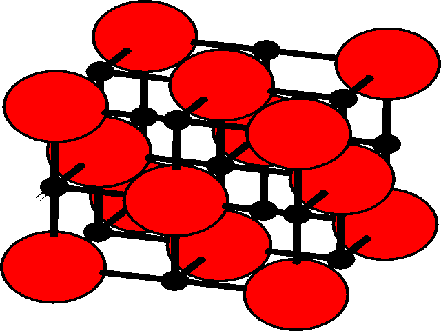
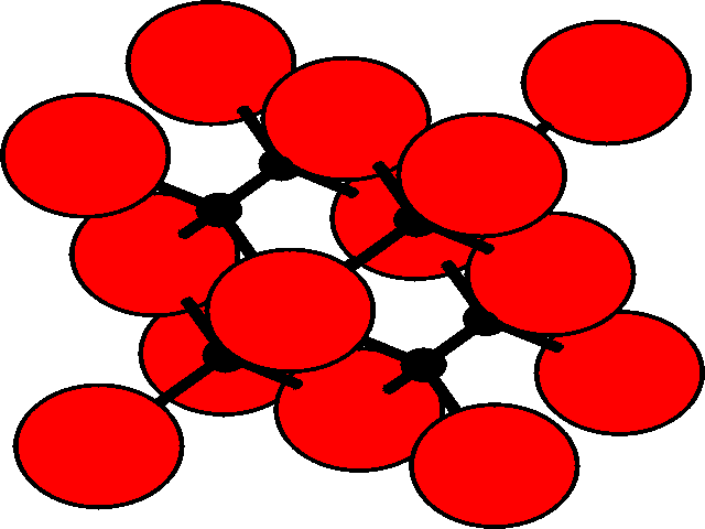
In the three dimensional lattice, these octahedral and tetrahedral holes occupy characteristic positions in the unit cell. These are shown for the fcc lattice.
| Position of holes in the fcc lattice | |
| Octahedral holesThe holes are shown as black, and the fcc array of spheres as red.
There is one octahedral hole for each atom in the fcc lattice. |
Tetrahedral holesThe holes are shown as black, and the fcc array of spheres as red.
There are two tetrahedral holes for each atom within the fcc lattice. |
 |
 |